Input/Output Configuration
The Configuration tab allows you to set up each input and output of your equipment: name, sensor type, calibration, units of measurement.
Accessing Configuration
- Access your equipment page
- Click on the "Configuration" tab
Interface Overview
The configuration interface consists of:
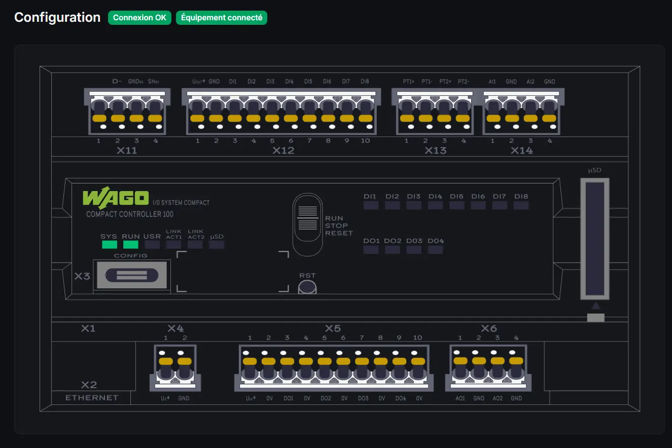
Left Zone: Graphical Representation
Visualization of the controller with modules and I/O status in real-time.
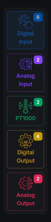
Right Zone: I/O List
Navigation between different input/output types via buttons:
- Digital Inputs
- Analog Inputs
- PT1000 Inputs
- Digital Outputs
- Analog Outputs
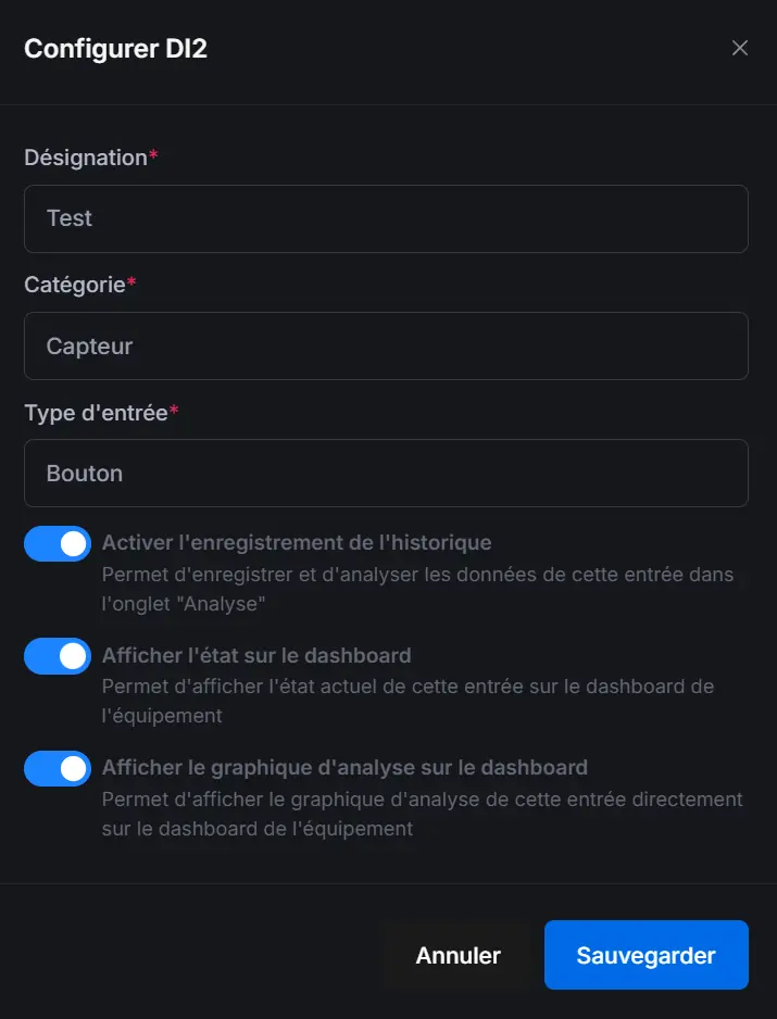
Configuring a Digital Input
Digital inputs are two-state sensors (ON/OFF).
Information to Fill
| Field | Description |
|---|---|
| Name | Input identifier (e.g., "Office presence detector") |
| Sensor Type | Selection from predefined or custom types |
| Icon | Visual representation |
Procedure
- Click on the digital input to configure (DI1, DI2, etc.)
- Enter the name
- Select the sensor type from the list
- Choose a representative icon
- Click on "Save"
An explicit name facilitates scenario creation and dashboard reading.
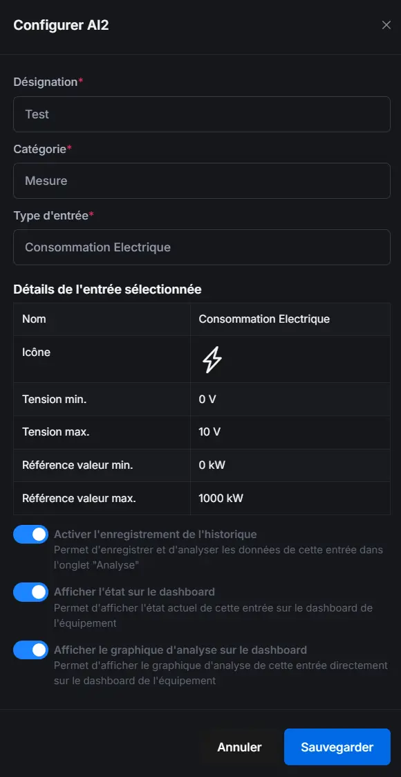
Configuring an Analog Input
Analog inputs measure continuous values (0-10V or 4-20mA).
Information to Fill
| Field | Description |
|---|---|
| Name | Input identifier |
| Sensor Type | Sensor category |
| Icon | Visual representation |
| Unit of Measurement | Displayed unit (%, lux, bar, etc.) |
| Min Voltage | Voltage corresponding to minimum value |
| Max Voltage | Voltage corresponding to maximum value |
| Min Value | Physical value at minimum voltage |
| Max Value | Physical value at maximum voltage |
Calibration
Calibration converts the read voltage (0-10V) into a physical value:
Example: Light sensor 0-10V = 0-1000 lux
- Min voltage: 0V → Min value: 0 lux
- Max voltage: 10V → Max value: 1000 lux
Advanced Calibration
For non-linear sensors, point-by-point calibration is available:
- Click on "Advanced Calibration"
- Add reference points (voltage → value)
- The system automatically interpolates between points

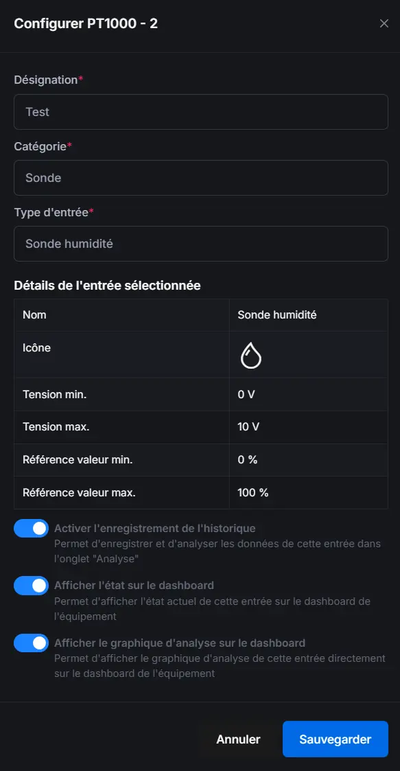
Configuring a PT1000 Input
PT1000 inputs are high-precision temperature probes.
Information to Fill
| Field | Description |
|---|---|
| Name | Probe identifier |
| Type | PT1000 probe type |
| Icon | Visual representation |
PT1000 Calibration
Offset calibration is available to adjust measurements:
- Place the probe in an environment at known temperature
- Note the difference between the read value and actual value
- Enter the correction offset
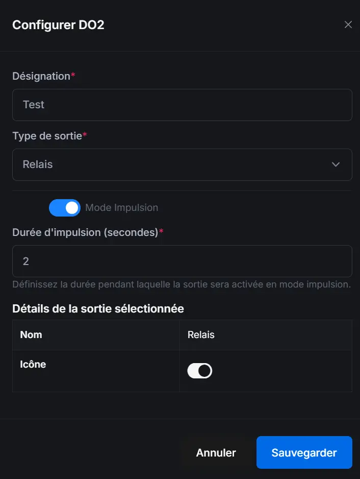
Configuring a Digital Output
Digital outputs control ON/OFF actuators.
Information to Fill
| Field | Description |
|---|---|
| Name | Output identifier |
| Actuator Type | Output category |
| Icon | Visual representation |
| Pulse Mode | Temporary activation |
| Pulse Duration | Duration in seconds (if pulse mode) |
Pulse Mode
Pulse mode allows activating the output for a defined duration:
- Enable the "Pulse Mode" option
- Define the duration in seconds
- At each activation, the output will turn off automatically after the duration
Use cases: Gate opening, door unlocking
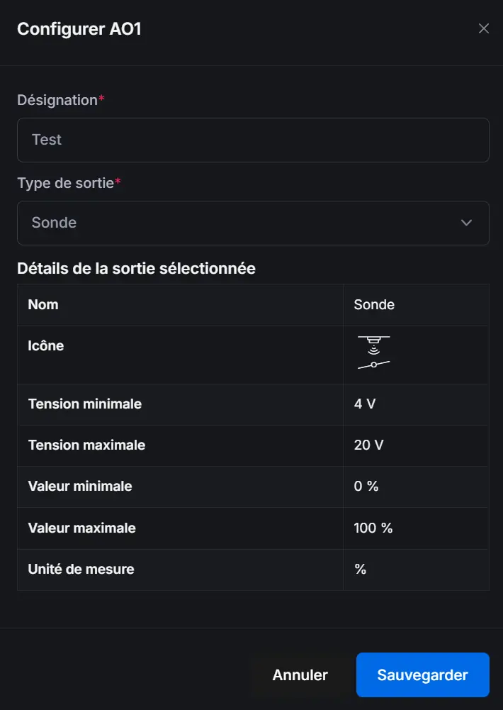
Configuring an Analog Output
Analog outputs control variable value actuators (0-10V).
Information to Fill
| Field | Description |
|---|---|
| Name | Output identifier |
| Actuator Type | Output category |
| Icon | Visual representation |
| Unit of Measurement | Displayed unit (%, °C, etc.) |
| Min Value | Value at 0V |
| Max Value | Value at 10V |
Enable History
For each input/output, you can enable history recording:
- In the I/O configuration, enable "Record history"
- Values will be stored for later consultation
- View the "Analysis" tab to see charts
History and analysis require a Basic or Premium subscription.
Custom Sensor Types
You can create your own sensor types from the "Sensors & Outputs" section of your client space.
Save Configuration
After each modification:
- Click on "Save"
- Configuration is saved to the database
- Changes are immediately visible on the dashboard
Configuration changes do not affect existing scenarios. Check your scenarios if you rename an I/O.
Accessing Configuration
- Access your equipment page
- Click on the "Configuration" tab
Interface Overview
The configuration interface consists of:
Left Area: Graphic Representation
Visualization of the controller with modules and real-time I/O states.
Right Area: I/O List
Navigation between different input/output types via buttons:
- Digital inputs
- Analog inputs
- PT1000 inputs
- Digital outputs
- Analog outputs
Configuring a Digital Input
Digital inputs are two-state sensors (ON/OFF).
Information to Fill In
| Field | Description |
|---|---|
| Name | Input identifier (e.g., "Office presence detector") |
| Sensor Type | Selection from predefined or custom types |
| Icon | Visual representation |
Procedure
- Click on the digital input to configure (DI1, DI2, etc.)
- Fill in the name
- Select the sensor type from the list
- Choose a representative icon
- Click on "Save"
An explicit name makes scenario creation and dashboard reading easier.
Configuring an Analog Input
Analog inputs measure continuous values (0-10V or 4-20mA).
Information to Fill In
| Field | Description |
|---|---|
| Name | Input identifier |
| Sensor Type | Sensor category |
| Icon | Visual representation |
| Measurement Unit | Displayed unit (%, lux, bar, etc.) |
| Min Voltage | Voltage corresponding to minimum value |
| Max Voltage | Voltage corresponding to maximum value |
| Min Value | Physical value at minimum voltage |
| Max Value | Physical value at maximum voltage |
Calibration
Calibration converts the read voltage (0-10V) into a physical value:
Example: Light sensor 0-10V = 0-1000 lux
- Min voltage: 0V → Min value: 0 lux
- Max voltage: 10V → Max value: 1000 lux
Advanced Calibration
For non-linear sensors, point-by-point calibration is available:
- Click on "Advanced Calibration"
- Add reference points (voltage → value)
- The system automatically interpolates between points
Configuring a PT1000 Input
PT1000 inputs are high-precision temperature probes.